The following procedure describes how to test the homing repeatability of an axis.
A dial indicator and magnetic base are required for this test.
Procedure
Home the machine
Jog the machine a known distance (i.e. 100mm) from the home position using the distance jog controls
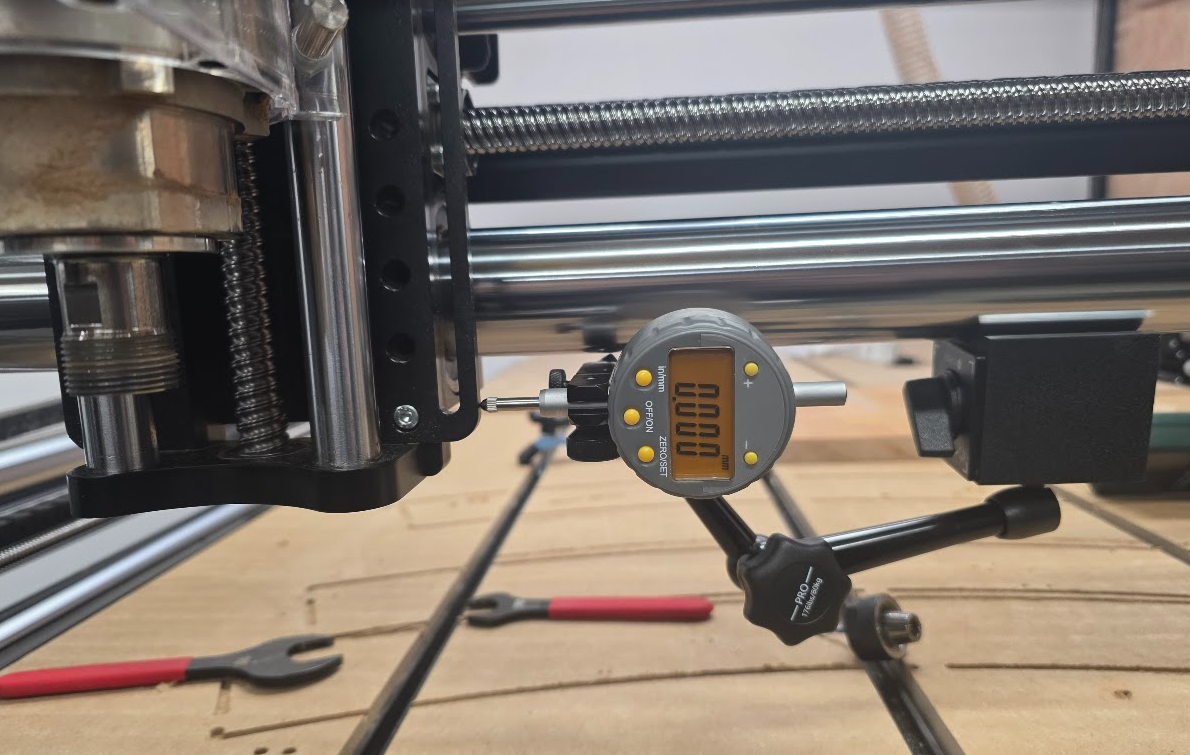
Set up a dial indictor parallel to the axis with the dial zero set to the 100mm position. A magnetic base can be used to attach the dial indicator directly to the axis rail.
Dial Indicator Setup
Home the axis that is being tested for repeatability.
Jog the machine back to the dial indicator position and read the new position from the dial indicator.
Position Repeatability
The dial indicator can be set up on the rail as described above in the homing repeatability test.
Procedure 10mm Test
Carefully jog the machine until it is just touching the dial indicator.
Zero the indicator position.
Jog the machine 10mm towards the dial and observe the travel distance on the dial.
Jog the machine 10mm away from the dial and check that the dial reads zero again.
Repeat the steps above and watch for any accumulating error after several iterations.
Note
Some inaccuracy in the final position is expected due to backlash and accuracy of the mechanical system.
We are looking for a pattern of drift in one direction after many iterations.
Note
The motor resolution can also be tweaked to dial in the travel and it will accept fractional values. If the movement is short by a fraction of a mm, try increasing the motor resolution slightly. e.g. If your motor resolution is 125 steps/mm you can increase it to 125.1 steps/mm
Procedure 1mm Test
Carefully jog the machine until it is just touching the dial indicator.
Zero the indicator position.
Jog the machine 10mm towards the dial in 1mm increments and observe the travel distance on the dial.
Jog the machine 10mm away from the dial in 1mm increments and check that the dial reads zero again.
Repeat the steps above and watch for any accumulating error after several iterations. Jogging using 1mm increments tests several start/stop (accelerate/decelerate) cycles.
Helical Boring Accuracy & Drift Test
A four hole helical boring toolpath is used to test the repeatability of the machine by running multiple passes.
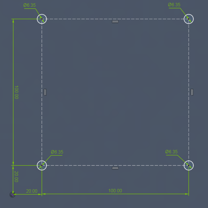
A 1/8" endmill is used to bore four 1/4" holes spaced on a square at 100mm spacing with a 20mm offset from the work origin. Each hole should be 10mm deep.
Helical Boring Toolpath Dimensions
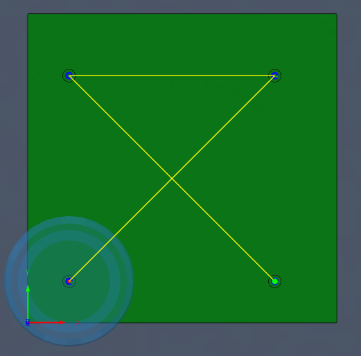
The toolpath is designed to bore each hole in two passes and to move along the diagonal to maximize rapid travel.
Procedure
Set your WCS zero to the lower left of the bore hole pattern with the Z height set to the top of the material.
Run the toolpath to bore the four 1/4" holes.
Check hole dimensions with a gauge pin.
Repeat the test and check that the machine position does not drift.
Note
A dial indicator can be set up to monitor the home position of any axis.
Test Files
Boring Test Toolpath
Four 1/4" holes bored to 10mm depth
Details: Cut to 0.25" depth in 5 passes (0.05" per pass).
Tool: 1/8" Flat Endmill
Download: Toolpath [Metric]
Download: Fusion 360 CAD File
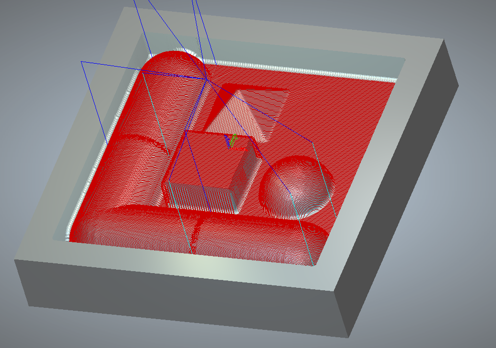
3D Raster Carve Test
This 3D carve test is split into multiple raster regions. The regions are intentionally separated so any positional shift will appear when
the next regions is started.
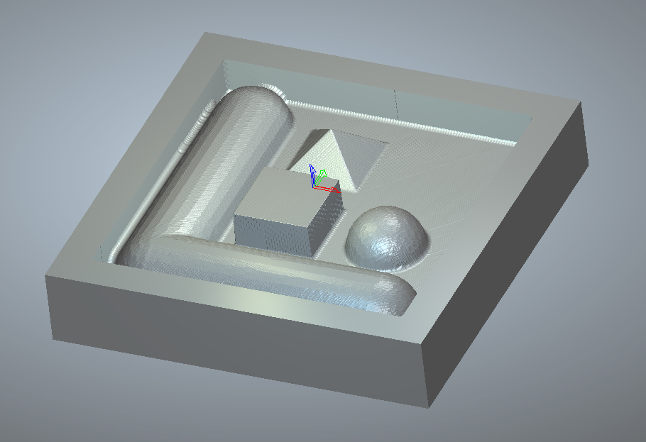
3D Benchmark Toolpath
The toolpath will carve a cylindrical tube, hemisphere, square prism and triangular prism. A flat bottom pocket area is also provided.
Procedure
The toolpath cutting area is 4" x 4" with a cutting depth of 1". Set your WCS origin to the center of this square area with the Z WCS origin set to the top of stock.
Run the toolpath and check for carving defects or position shifts between raster areas.
Test Files
3D Benchmark Toolpath
3D Benchmark Toolpath
Details: Cuts 3D shapes in multiple raster regions
Tool: 1/8" Ball Endmill
Download: Toolpath [Imperial]
Download: Carveco CAD File
Other Test Files
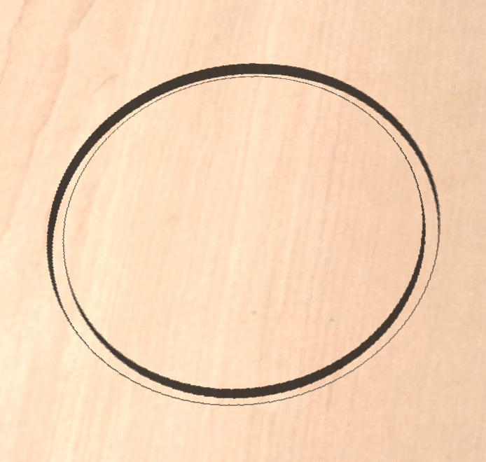
Circle Test Cut
Circle with 6" diameter
Details: Cut to 0.25" depth in 5 passes (0.05" per pass).
Tool: 1/4" Flat Endmill
Download: CircleTest.ngc [Imperial]
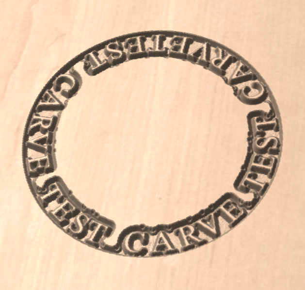
VCarve Test Cut
Vcarved Text in 6" Circle
Details: Cut to 0.15" depth in 3 passes (0.05" per pass).
Tool: 1/4" 60° V-bit
Download: TextTest.ngc [Imperial]